


SPDT (Single Pole Double Throw) switches, or single-pole double-throw switches, have a common terminal and two independent selector terminals. The common terminal can be connected to one of these two selector terminals when the switch is in a different position. The following is a description of the SPDT switch connections and a simple circuit diagram:
Connection Description:
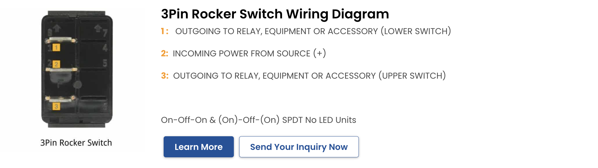
Common: This is a fixed connection point of the switch, usually indicated by the letter “C” or the number “1”.
Throw 1: This is a movable connection point of the switch, when the switch is in a certain position, the common terminal will be connected to this selective terminal. Usually indicated by the letter “A” or the number “2”.
Throw 2: This is the other movable connection point of the switch. When the switch is in another position, the common terminal is connected to this selector terminal. This is usually indicated by the letter “B” or the number “3”.
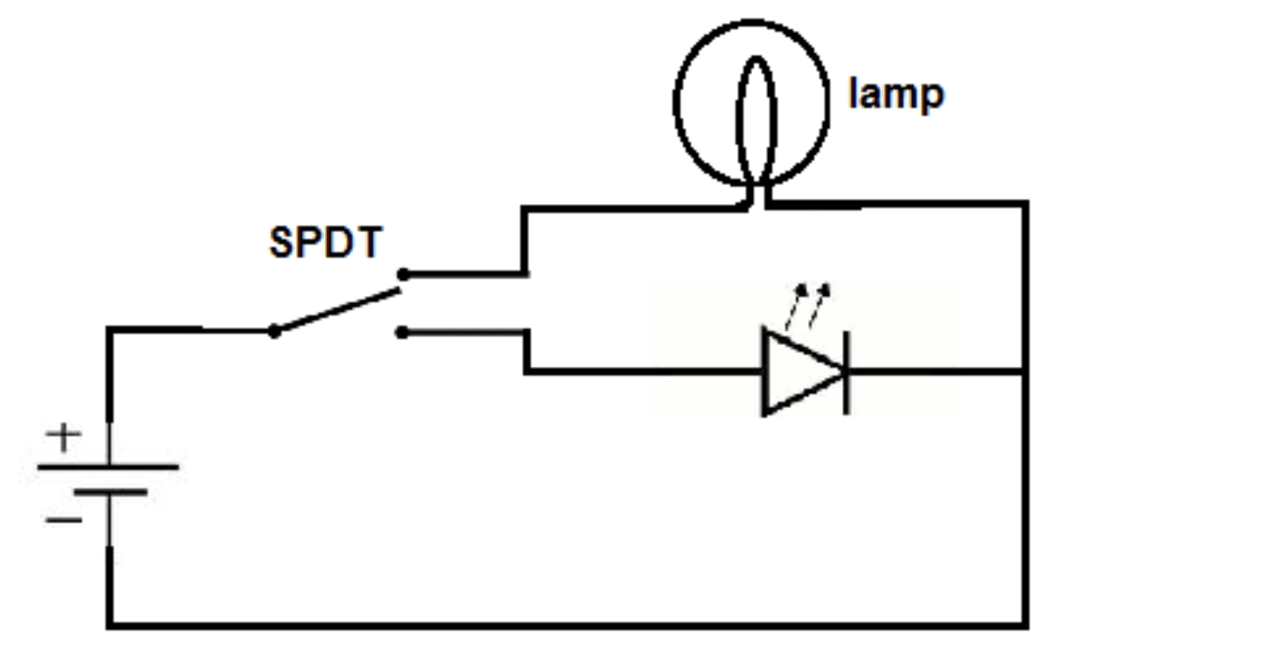
Circuit diagram example:
(Since it is not possible to draw a circuit diagram directly here, I will describe a simple circuit diagram in words)
Draw a switch symbol, usually a rectangle or circle with a movable arrow or contact inside.
On one side of the switch symbol, draw a common terminal (C or 1) with a wire connected to the positive terminal of the power supply (e.g. +12V).
On the other side of the switch symbol, draw two selector terminals (A or 2 and B or 3).
Draw a line from selector A (or 2) to one end of a load (e.g., a light bulb), and then draw a line from the other end of this load to the negative terminal of the power supply (e.g., 0V or GND).
Draw a line from selector B (or 3) to one end of another load (e.g., another light bulb) and then draw a line from the other end of this load to the negative terminal of the power supply.
When the arrow or contact of the switch points to selector A (or 2), the power supply will be connected to the first load to make it work. When the arrow or contact of the switch points to selector B (or 3), the power supply will connect to the second load to make it work.
This is the basic connection and circuit diagram example of SPDT switch. In practice, you can make more complex connections and configurations to suit your specific needs.
Translated with DeepL.com (free version)