


The wiring diagram for an ON/OFF switch is relatively simple, typically involving two main parts: the power line and the load line. When wiring, one end of the power line needs to be connected to one terminal of the switch, and one end of the load line needs to be connected to the other terminal of the switch. The other ends of the power line and the load line are then connected to the power source and the load, respectively.
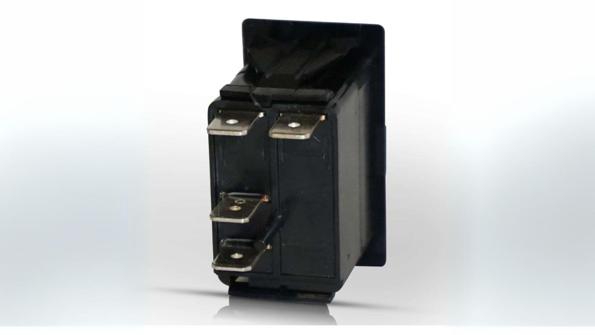
LED Rocker Switch Wiring Diagram
When wiring an LED rocker switch, the power supply for the LED needs to be considered. Below is a typical wiring procedure and schematic:
- Determine Switch Type:
- First, confirm the type of rocker switch, such as SPST (Single Pole Single Throw), DPST (Double Pole Single Throw), etc., and whether it comes with an LED indicator.
- Wiring Preparation:
- Prepare the power line, load line, and LED power line.
- Ensure that the voltage and current of the power line and load line meet the rated voltage and current requirements of the switch.
- Wiring Steps:
- Connect the positive pole (usually red) of the power line to the input power terminal of the switch (usually marked as “IN” or “+”).
- If the LED is integrated with the switch, connect its positive pole to the input power terminal of the switch, or connect it to the dedicated LED power terminal according to the switch design.
- Connect the negative pole (usually black or blue) of the power line to the negative pole of the circuit (usually marked as “-” or “GND”).
- Connect the positive pole of the load line to the output terminal of the switch (usually marked as “OUT” or the corresponding load symbol).
- Connect the negative pole of the load line to the negative pole of the circuit.
- Precautions:
- Before wiring, ensure that the power is turned off to avoid electric shock or other accidents.
- Follow the wiring diagram or instruction manual of the switch to ensure correct wiring.
- Ensure that the wiring terminals are securely tightened to avoid poor contact or short circuits that may cause equipment failure.
Wiring Diagram Example
Due to variations in switch models and brands, the following is a simplified schematic to illustrate the basic concept:
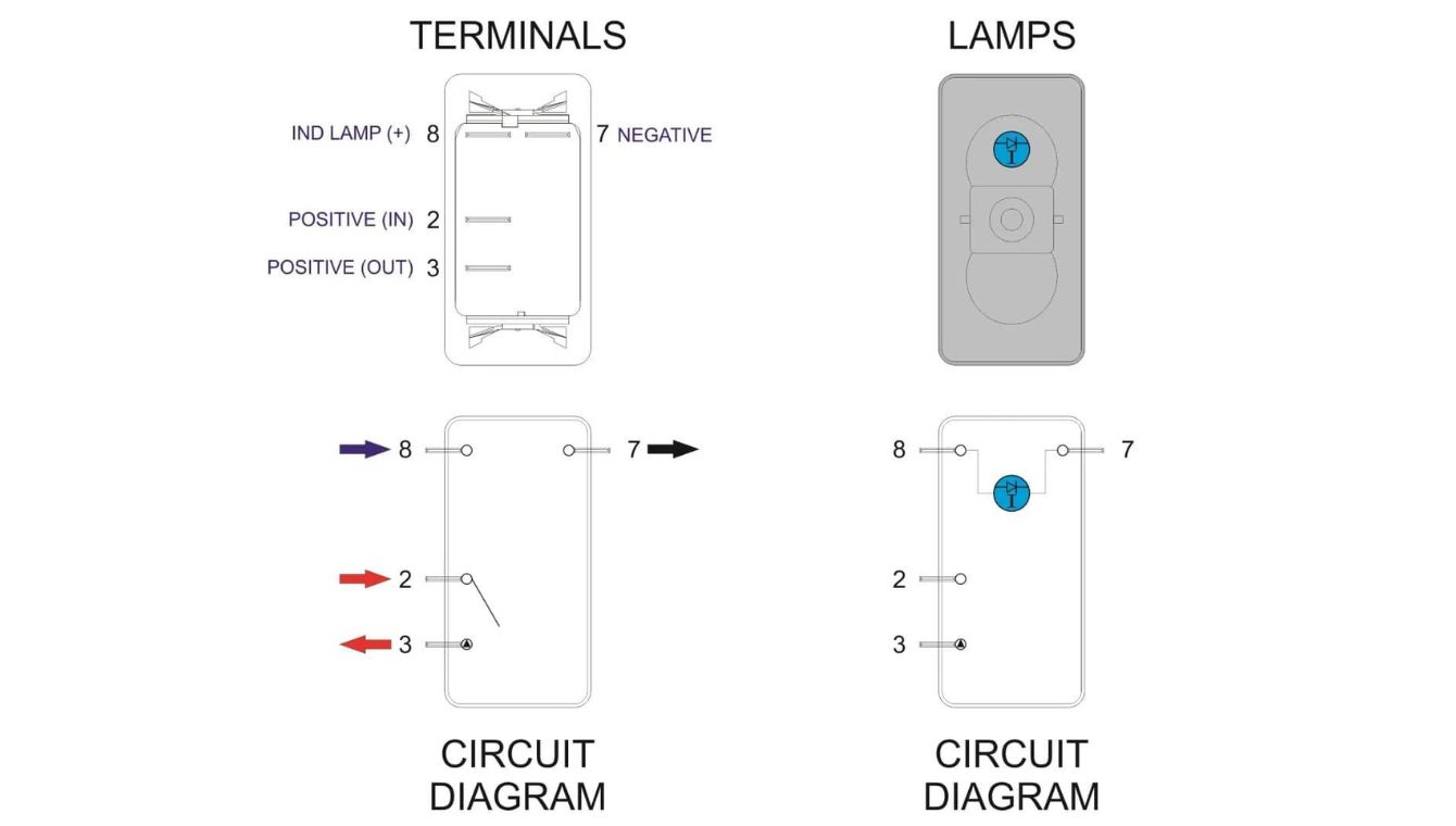

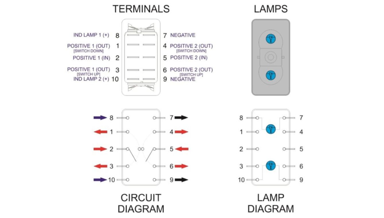
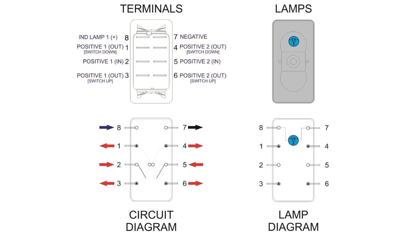
Please note that the above schematic is a simplified representation, and the actual wiring diagram may vary depending on the specific design and functionality of the switch. Therefore, before wiring, be sure to refer to the wiring diagram or instruction manual provided by the switch manufacturer.
For specific wiring diagrams, it is recommended to consult the official documentation provided by the switch manufacturer or contact technical support for accurate information. Additionally, you can search for wiring diagrams of similar switches in professional electronic forums or communities for reference.