


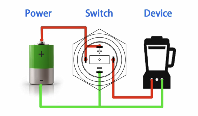
Connect the positive pole of the power supply to the load pin of the switch, and connect the other load pin to the LED lamp pin (+) and the positive pole of the device, and then connect the negative pole of the power supply to the negative pole of the LED lamp pin. The LED inside the button lights up. When the hand leaves the button, the button is powered off. Please look at the drawing.
The picture below is a schematic diagram of push button switch connected to the device
Button function:
The switch is locked and the light is on, and the device starts.
The switch reset light is off, and the device is turned off.
Wiring:
1. The positive pole ofthe power supply is connected to the load pin ofthe switchand the other load pin is connected to the LED light pin (+) and the positive pole ofthe device.
2. Connect the negative pole ofthe power supply to the negative pole ofthe deviceand the LED lamp pin (-)..
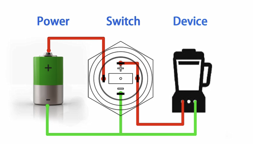
Button function:
The switch is locked and the device starts.The switch is reset, the device is turned off,
and the light is always on.
Wiring:
1.The positive pole ofthe power supply is connected to the switch load pin andthe LED lamp pin (+), and the other load pin is connected to the positive pole ofthe device.
2. Connect the negative pole ofthe power supply to the negative pole ofthe deviceand the LED lamp pin (-).