


Contents hide
In the world of electrical engineering and circuit design, switches serve as fundamental control components that enable or disable the flow of electricity. Among the various types of switches available, the Single Pole Single Throw (SPST) switch stands out as one of the most commonly used and versatile options. Whether you’re designing an electronic circuit, working on an automotive electrical system, or simply trying to understand the basics of electrical controls, understanding SPST switches is essential.
This comprehensive guide explores everything you need to know about Single Pole Single Throw switches – from basic concepts and working principles to applications, selection criteria, installation best practices, and troubleshooting tips. By the end of this guide, you’ll have a thorough understanding of SPST switches and be well-equipped to make informed decisions for your specific requirements.

What Are Single Pole Single Throw (SPST) Switches?
Definition and Basic Concept
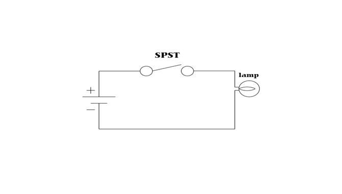
A Single Pole Single Throw (SPST) switch is the simplest form of electrical switch, characterized by having one input terminal (pole) and one output terminal (throw). The term “single pole” indicates that the switch controls just one electrical circuit, while “single throw” means there is only one possible output connection when the switch is in the “ON” position.
In its most basic form, an SPST switch functions as a simple ON/OFF control mechanism. When the switch is in the “ON” position, it creates a connection between the input and output terminals, allowing current to flow and completing the circuit. When switched to the “OFF” position, the connection is broken, current flow stops, and the circuit is interrupted.
The classic example of an SPST switch is the standard light switch in your home. When you flip it up, the circuit completes, and the light turns on. When you flip it down, the circuit breaks, and the light turns off.
The internal structure of an SPST switch typically consists of two conductive contacts that either touch (closed circuit) or separate (open circuit) based on the switch position. These contacts are usually made of durable, conductive materials like copper alloys or silver to ensure reliable electrical connections and long service life.
[IMAGE SUGGESTION: Cross-section diagram of an SPST switch showing internal components and contact positions in both ON and OFF states]
How SPST Switches Work
The working principle of an SPST switch is straightforward yet elegant in its simplicity. When the switch actuator (the part you physically interact with, such as a toggle, button, or slider) is moved to the “ON” position, it mechanically brings the two electrical contacts together. This creates a conductive path, allowing electricity to flow through the switch and into the connected circuit.
The electrical characteristics of the switch in its “ON” state include low contact resistance (typically in the milliohm range) to minimize power loss and heat generation. When properly designed, an SPST switch in the “ON” position should present minimal impedance to the circuit.
Conversely, when the switch is moved to the “OFF” position, the actuator mechanically separates the contacts, creating an air gap between them. This gap acts as an insulator, preventing current flow. In the “OFF” state, the switch presents extremely high resistance (ideally infinite), effectively breaking the circuit.
The mechanical action that drives this connection and disconnection varies by switch type. In toggle switches, a lever mechanism converts the rotational motion of the toggle to linear motion that connects or disconnects the contacts. In pushbutton switches, a spring-loaded mechanism creates temporary or latching connections based on the design.
[IMAGE SUGGESTION: Animated diagram showing the movement of switch contacts during operation]
Types of Single Pole Single Throw Switches
SPST switches come in various forms, each designed for specific applications and environments. Understanding the different types will help you select the most appropriate switch for your needs.
Toggle SPST Switches
Toggle SPST switches are perhaps the most recognizable type, featuring a lever or handle that can be flipped between two positions. These switches are widely used in applications requiring a clear visual indication of the switch state and easy actuation.
Common specifications for toggle SPST switches include:
- Current ratings typically ranging from 1A to 20A
- Voltage ratings from 12V DC to 250V AC
- Various handle styles including standard, locking, illuminated, and waterproof options
- Terminal types including solder, quick-connect, screw, and PCB mount
Toggle switches excel in applications where durability and ease of operation are priorities. They’re commonly found in automotive dashboards, industrial control panels, and marine applications where operators may be wearing gloves or working in challenging conditions.
The main advantages of toggle switches include their robust construction, clear tactile feedback, and excellent visibility of switch position. However, they require more panel space than other switch types and may not be suitable for applications where accidental actuation is a concern.
[IMAGE SUGGESTION: Photo of various toggle SPST switches showing different styles and sizes]
Rocker SPST Switches
Rocker SPST switches feature a see-saw-like mechanism that rocks between two positions. These switches have become increasingly popular in modern applications due to their sleek appearance and ease of operation.
Typical specifications include:
- Current ratings from 6A to 16A
- Voltage ratings up to 250V AC
- Various sizes from miniature (13mm x 19mm) to standard (19mm x 22mm) and large (30mm x 22mm)
- Options for illumination, markings, and splash resistance
Rocker switches are commonly used in household appliances, power strips, computer peripherals, and modern automotive applications. Their flush mounting and attractive appearance make them ideal for consumer-facing products.
The advantages of rocker switches include their modern aesthetics, resistance to dust infiltration, and ease of cleaning. Their main limitations include less distinct tactile feedback compared to toggle switches and potentially less durability in extremely harsh environments.
[IMAGE SUGGESTION: Photo of rocker switches in various applications, showing their integration into modern devices]

Push Button SPST Switches
Push button SPST switches are actuated by pressing a button that either latches (maintains its state until pressed again) or momentarily changes state (returns to its original position when released).
Key specifications include:
- Current ratings from 0.1A (signal level) to 10A (power applications)
- Voltage ratings from 5V DC (electronics) to 250V AC (mains applications)
- Actuation types: momentary or latching
- Button shapes: round, square, rectangular, or custom
- Various mounting options including panel mount, PCB mount, and snap-in
Push button switches are extensively used in electronics, industrial control systems, security applications, and user interfaces. Momentary versions are common in doorbell buttons, keyboard keys, and test equipment, while latching versions are used for power controls and mode selection.
The primary advantages of push button switches include their intuitive operation, compact footprint, and versatility in design. Their limitations may include less visibility of switch state (unless illuminated) and potential for wear in high-frequency usage applications.
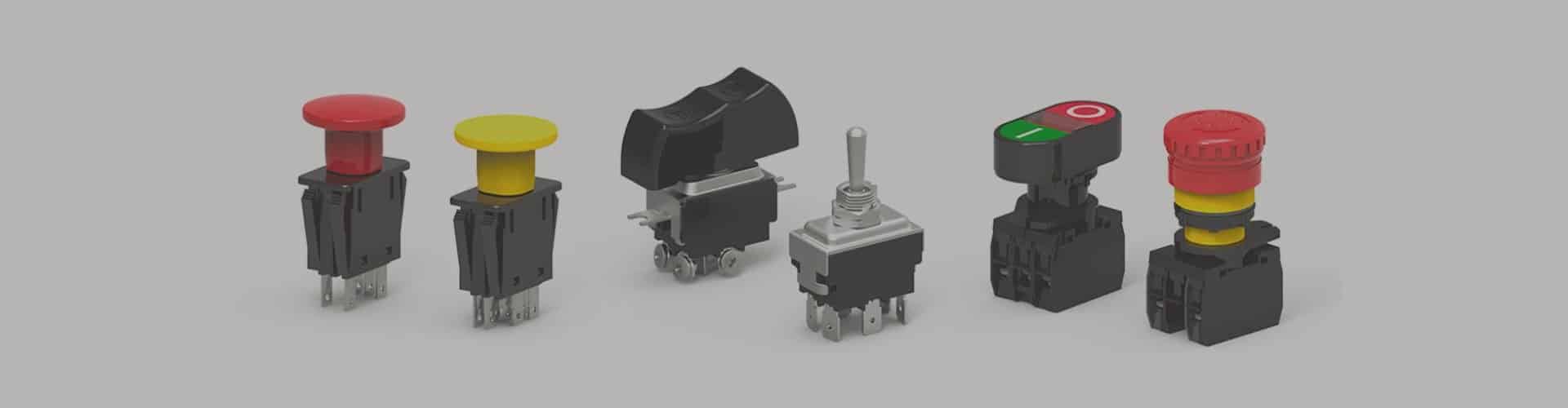
[IMAGE SUGGESTION: Collection of different push button switches showing variety in size, color, and design]
Slide SPST Switches
Slide SPST switches operate by sliding a small actuator between two positions. These switches are typically compact and low-profile, making them ideal for space-constrained applications.
Common specifications include:
- Current ratings from 0.3A to 6A
- Voltage ratings from 5V DC to 125V AC
- Various slider sizes and styles
- Mounting options including PCB mount, panel mount, and surface mount
Slide switches are frequently used in consumer electronics, toys, small appliances, and test equipment. They’re particularly common in battery-powered devices where space is limited and current requirements are modest.
The advantages of slide switches include their low profile, economical cost, and smooth operation. Their limitations include lower current handling capacity compared to toggle or rocker switches and potentially less durability under frequent use.
[IMAGE SUGGESTION: Close-up of slide switches on electronic devices, showing their compact integration]
Knife SPST Switches
Knife SPST switches, also known as disconnect switches, feature a hinged blade that makes or breaks contact with a stationary clip. These switches are among the oldest designs still in use today.
Typical specifications include:
- Current ratings from 15A to several hundred amperes
- Voltage ratings up to 600V AC
- Open blade or enclosed designs
- Various mounting options including panel mount and base mount
Knife switches are primarily used in educational demonstrations, laboratory settings, high-current applications, and some industrial environments. Their open design allows for visual confirmation of the connection state.
The main advantages of knife switches include their high current handling capacity, visual indication of state, and simplicity of design. Their limitations include safety concerns due to exposed contacts (in open designs), larger size compared to other switch types, and slower operation.
[IMAGE SUGGESTION: Photo of a knife switch in both open and closed positions, highlighting the blade mechanism]
SPST Switches vs. Other Switch Types
Understanding how SPST switches compare to other common switch configurations will help you determine the most appropriate type for your specific application.

SPST vs. SPDT Switches
Single Pole Double Throw (SPDT) switches differ from SPST switches in that they have one input (pole) and two possible output connections (throws). While an SPST switch provides simple ON/OFF functionality, an SPDT switch allows for selecting between two different circuits or paths.
Key differences include:
- SPST switches have two terminals (one input, one output), while SPDT switches have three terminals (one input, two outputs)
- SPST switches can only be in an ON or OFF state, while SPDT switches can connect the input to either of two outputs
- SPDT switches can be configured for ON-ON operation (always connected to one output or the other) or ON-OFF-ON operation (center position disconnects all)
SPDT switches are ideal for applications requiring selection between two options, such as directing a signal to one of two destinations, selecting between two power sources, or controlling a reversible motor. Common examples include three-way light switches in homes and selector switches in audio equipment.
Choose an SPST switch when you need simple ON/OFF control of a single circuit. Choose an SPDT switch when you need to select between two different circuits or create more complex control schemes.
[IMAGE SUGGESTION: Comparison diagram showing SPST and SPDT switch configurations and circuit symbols]
SPST vs. DPST Switches
Double Pole Single Throw (DPST) switches effectively combine two SPST switches that are mechanically linked to operate simultaneously. They have two inputs (poles) and two outputs (throws), allowing them to control two separate circuits with a single actuation.
Key differences include:
- SPST switches control one circuit, while DPST switches control two independent circuits simultaneously
- DPST switches have four terminals (two inputs, two outputs), compared to the two terminals of an SPST switch
- DPST switches are ideal for applications where two electrically isolated circuits must be controlled together
DPST switches are commonly used in applications such as controlling both the hot and neutral lines in AC power applications, simultaneously switching multiple signals, or providing status indication alongside power control.
Choose an SPST switch for controlling a single circuit. Choose a DPST switch when you need to simultaneously control two electrically isolated circuits with one switch action.
[IMAGE SUGGESTION: Diagram comparing SPST and DPST switches, showing terminal configurations and circuit control]
SPST vs. DPDT Switches
Double Pole Double Throw (DPDT) switches represent the most complex of these common configurations. They feature two inputs (poles) and four outputs (two throws for each pole), allowing for complex switching arrangements.
Key differences include:
- DPDT switches have six terminals compared to SPST’s two terminals
- DPDT switches can control two independent circuits, each with two possible connection paths
- DPDT switches offer the most flexibility but are larger and more expensive than SPST switches
DPDT switches excel in applications requiring complex control schemes, such as reversing motor direction, crossover switching in audio applications, or transfer switching between power sources.
Choose an SPST switch for simple ON/OFF control. Choose a DPDT switch when you need the maximum flexibility to control multiple circuits with multiple possible states.
[IMAGE SUGGESTION: Comprehensive comparison chart of all switch types (SPST, SPDT, DPST, DPDT) with circuit diagrams]
Key Features and Specifications of SPST Switches
When selecting an SPST switch for your application, understanding the key specifications and features is essential to ensure proper performance and reliability.
Electrical Ratings
The electrical ratings of an SPST switch determine its capacity to safely handle current and voltage in your application.
Voltage Rating: This specification indicates the maximum voltage the switch can safely handle. Exceeding this rating can lead to arcing, insulation breakdown, and switch failure. Common voltage ratings include:
- Low voltage: 12V, 24V, 48V DC
- Mains voltage: 120V, 240V AC
- High voltage: 277V, 480V AC for industrial applications
Current Rating: This specification defines the maximum current the switch can carry continuously without overheating. Exceeding the current rating can cause contact welding, overheating, and premature failure. Common current ratings include:
- Signal level: 0.1A to 1A
- Control level: 1A to 5A
- Power level: 5A to 20A
- Heavy-duty: 20A and above
Contact Resistance: This parameter measures the electrical resistance across the closed switch contacts, typically expressed in milliohms. Lower contact resistance results in less power loss and heat generation. Quality switches typically offer contact resistance below 50 milliohms.
Insulation Resistance: This specification indicates how well the switch prevents current leakage when in the open position. Higher values (typically measured in megohms) indicate better insulation properties.
For applications involving inductive loads (motors, solenoids, transformers), it’s important to consider the switch’s inductive load rating, which is typically lower than its resistive load rating due to the challenges of interrupting inductive currents.
[IMAGE SUGGESTION: Chart showing relationship between voltage, current ratings and switch size/type]
Contact Configurations
SPST switches come in different contact configurations that determine their behavior and suitability for specific applications.
Normally Open (NO): In this configuration, the switch contacts are open (disconnected) when the switch is in its relaxed or non-actuated state. The circuit is completed only when the switch is actuated. This configuration is common in applications where the default state should be “OFF,” such as doorbell buttons, start buttons, and most power switches.
Normally Closed (NC): In this configuration, the switch contacts are closed (connected) when the switch is in its relaxed or non-actuated state. The circuit is broken when the switch is actuated. This configuration is used in applications where the default state should be “ON,” such as emergency stop buttons, safety interlocks, and alarm circuits.
Momentary Contact: These switches change state only while being actuated and return to their default position when released. They come in both normally open (push-to-make) and normally closed (push-to-break) variants. Momentary switches are used in applications requiring temporary activation, such as doorbell buttons, keyboard keys, and test buttons.
Maintained Contact: These switches remain in their last position until manually changed. They provide stable ON or OFF states without requiring continuous actuation. Most toggle, rocker, and slide switches are maintained contact types.
The contact material significantly affects switch performance and longevity. Common contact materials include:
- Silver alloys: Excellent conductivity and moderate corrosion resistance
- Gold-plated contacts: Superior corrosion resistance for low-current applications
- Silver-cadmium oxide: Excellent arc suppression for high-current applications
- Silver-nickel: Good balance of conductivity and durability
[IMAGE SUGGESTION: Diagram showing different contact configurations (NO/NC) and their states during actuation]
Environmental Specifications
Environmental specifications determine a switch’s suitability for operation in various conditions and environments.
IP Rating (Ingress Protection): This standardized rating indicates the switch’s resistance to solid objects and liquids. For example:
- IP40: Protected against solid objects over 1mm, no water protection
- IP65: Totally protected against dust, protected against low-pressure water jets
- IP67: Totally protected against dust, protected against temporary immersion
- IP68: Totally protected against dust, protected against continuous immersion
Operating Temperature Range: This specification defines the temperature range within which the switch will function reliably. Typical ranges include:
- Commercial grade: 0°C to +70°C
- Industrial grade: -20°C to +85°C
- Extended range: -40°C to +125°C
Vibration and Shock Resistance: These specifications indicate the switch’s ability to withstand mechanical stresses without malfunction. They’re particularly important in automotive, aerospace, and industrial applications where equipment may be subject to significant vibration or impact.
Environmental Testing Standards: Quality switches are tested according to established standards such as:
- MIL-STD-202: Test methods for electronic and electrical components
- IEC 60068: Environmental testing procedures
- UL 1054: Standard for special-use switches
For harsh environment applications, look for switches with sealed construction, corrosion-resistant materials, and appropriate certifications for the intended operating conditions.
[IMAGE SUGGESTION: Visual representation of IP ratings and what they mean for switch protection]
Physical Dimensions and Mounting Options
The physical characteristics of an SPST switch determine how it will integrate into your device or system.
Standard Dimensions: Switches come in various standardized sizes, including:
- Miniature: Typically under 10mm in actuator dimension
- Standard: Common panel-mount sizes like 12mm, 15mm, or 19mm diameter
- Large: Industrial sizes for heavy-duty applications
Panel Mounting Options:
- Threaded bushing mount: Requires a round hole and secures with a nut
- Snap-in mount: Uses flexible tabs to secure in a shaped cutout
- Screw mount: Attaches via mounting holes on a flange or bracket
- Adhesive mount: Uses adhesive backing for surface mounting
PCB Mounting Options:
- Through-hole: Pins insert through holes in the PCB and are soldered on the opposite side
- Surface mount: Terminals attach directly to pads on the PCB surface
- Right-angle mount: Actuator extends perpendicular to the PCB
- Vertical mount: Actuator extends parallel to the PCB
Installation Considerations:
- Panel thickness compatibility
- Required behind-panel clearance
- Front panel sealing requirements
- Accessibility for operation
- Orientation constraints
When selecting a switch, ensure that its physical dimensions and mounting style are compatible with your enclosure design, panel thickness, and space constraints.
[IMAGE SUGGESTION: Diagram showing different mounting options for SPST switches in various applications]
Applications of SPST Switches
SPST switches find applications across numerous industries and products due to their simplicity, reliability, and versatility.
Automotive and Marine Applications
In automotive and marine environments, SPST switches must withstand vibration, temperature extremes, moisture, and potentially corrosive conditions.
Vehicle Electrical Systems:
- Headlight and auxiliary lighting controls
- Accessory power controls (radios, fans, heated seats)
- Engine start/stop buttons in modern vehicles
- Emergency disconnect switches
- Aftermarket accessory controls
Marine Control Systems:
- Navigation and anchor light controls
- Bilge pump controls
- Marine electronics power switches
- Battery disconnect switches
- Windlass and thruster controls
Special Requirements and Solutions:
- Waterproof or splash-resistant designs (typically IP65 or higher)
- Illuminated switches for nighttime visibility
- Heavy-duty construction to withstand vibration
- Corrosion-resistant materials for salt environments
- High current capacity for direct control of motors and high-power accessories
In a typical automotive application, SPST switches might control auxiliary lighting systems. These switches must handle the inrush current of the lights, provide clear ON/OFF indication to the driver, and maintain reliable operation despite constant vibration and temperature fluctuations. Waterproof toggle or rocker switches with illuminated actuators are commonly used for this purpose.
[IMAGE SUGGESTION: Photo of SPST switches in automotive dashboard and marine control panel applications]
Industrial Control Systems
Industrial applications demand switches that offer exceptional reliability, safety, and durability, often in challenging environments.
Control Panel Applications:
- Machine power controls
- Process start/stop functions
- Mode selection
- Emergency stop circuits (using NC contacts)
- Indicator and alarm reset functions
Machinery Equipment Control:
- Motor starters and disconnects
- Conveyor controls
- Pump and compressor controls
- Heating element controls
- Safety interlock systems
Safety System Applications:
- Emergency stop buttons
- Guard door interlocks
- Limit switches for position detection
- Operator presence controls
- Override and bypass controls
In industrial settings, SPST switches often serve as the primary interface between operators and machinery. For example, in a manufacturing line control panel, heavy-duty SPST switches might control individual stations or functions. These switches typically feature robust construction, clear position indication, and often include provisions for lockout/tagout procedures to prevent unauthorized operation during maintenance.
[IMAGE SUGGESTION: Industrial control panel with various SPST switches labeled for different functions]
Home Appliances and Electronics
Consumer products require switches that are economical, aesthetically pleasing, and user-friendly while maintaining adequate performance.
Home Appliance Applications:
- Power ON/OFF controls
- Function selection
- Temperature and speed controls
- Safety interlocks
- Door and lid switches
Consumer Electronics Applications:
- Power switches
- Mode selection
- Volume and brightness controls
- Battery compartment switches
- Reset buttons
Lighting Control Systems:
- Wall switches
- Lamp switches
- Smart lighting controls
- Dimmer activation
- Scene selection
In home environments, SPST switches must balance functionality with aesthetics and user experience. For example, a modern coffee maker might use an illuminated rocker switch as its main power control. This switch needs to be easy to clean, visually appealing, and provide clear feedback to the user, while still reliably controlling the appliance’s power circuit.
[IMAGE SUGGESTION: Collection of SPST switches in various home appliances and consumer electronics]
Specialized Applications
Beyond the common applications, SPST switches serve critical functions in specialized and high-reliability environments.
Medical Equipment Applications:
- Patient control interfaces
- Equipment power controls
- Mode selection
- Emergency shutdown
- Foot pedal controls
Aerospace Applications:
- Cockpit controls
- System activation switches
- Override controls
- Test and maintenance functions
- Ground support equipment
Military and Defense Systems:
- Weapons system controls
- Communications equipment
- Vehicle and vessel controls
- Field equipment
- Tactical systems
These specialized applications often require switches that meet stringent standards for reliability, environmental resistance, and performance verification. For instance, a military communications system might use sealed, illuminated SPST switches with guards to prevent accidental activation. These switches would be qualified to military standards for shock, vibration, temperature extremes, and electromagnetic compatibility.
[IMAGE SUGGESTION: Specialized SPST switches used in medical, aerospace, and military applications]
How to Choose the Right SPST Switch
Selecting the appropriate SPST switch for your application involves careful consideration of electrical, mechanical, environmental, and economic factors.
Understanding Your Application Requirements
Before selecting a switch, thoroughly analyze your application’s specific needs and constraints.
Electrical Parameter Requirements:
- Operating voltage (maximum and nominal)
- Current requirements (steady-state, inrush, and breaking capacity)
- AC or DC operation
- Inductive or resistive load characteristics
- Signal level or power switching
Environmental Condition Considerations:
- Operating temperature range
- Exposure to moisture, dust, or chemicals
- Vibration and shock exposure
- Indoor or outdoor use
- Altitude considerations
Operation Frequency and Lifetime Requirements:
- Expected number of operations over product life
- Frequency of switching operations
- Mechanical durability needs
- Electrical endurance requirements
- Failure consequences
Space and Installation Constraints:
- Available panel space
- Behind-panel depth limitations
- Mounting method compatibility
- Accessibility requirements
- Orientation needs
When evaluating these requirements, consider both normal operating conditions and potential extreme scenarios. For example, a switch for outdoor equipment must function not only in typical weather but also during temperature extremes, heavy rain, or dusty conditions.
[IMAGE SUGGESTION: Decision flowchart for selecting the appropriate SPST switch based on application requirements]
Quality and Reliability Factors
The quality and reliability of a switch significantly impact the performance and longevity of your entire system.
Manufacturer Reputation and Quality Control:
- Established s with proven track records
- Quality management systems (ISO 9001, etc.)
- Statistical process control implementation
- Traceability and lot control
- Warranty and support policies
Certifications and Standards Compliance:
- UL/CSA/VDE safety certifications
- RoHS and REACH environmental compliance
- Industry-specific standards (automotive, medical, military)
- Regional compliance (CE marking, CCC, etc.)
- Material safety documentation
Lifecycle Testing:
- Mechanical operation cycles
- Electrical endurance at rated load
- Contact resistance stability
- Environmental stress testing
- Accelerated life testing
Reliability Metrics:
- Mean Time Between Failures (MTBF)
- Failure rate data
- Expected service life
- Failure mode analysis
- Statistical reliability data
When comparing s, consider not just the initial quality but the consistency of production and long-term reliability. Major switch s like Honeywell, C&K, E-Switch, NKK, and Omron have established reputations for quality and provide comprehensive technical data to support their products.
[IMAGE SUGGESTION: Comparison chart of quality metrics for premium vs. standard SPST switches]
Cost-Benefit Analysis
Balancing cost considerations with performance requirements is essential for cost-effective design.
Initial Cost vs. Long-term Reliability:
- Purchase per unit
- Installation cost and complexity
- Expected service life
- Replacement cost and availability
- Downtime cost in case of failure
Maintenance and Replacement Considerations:
- Ease of replacement
- Availability of spare parts
- Cleaning and maintenance requirements
- Field serviceability
- Obsolescence risk
Volume Purchasing Strategies:
- Quantity discount thresholds
- Inventory carrying costs
- Just-in-time availability
- Minimum order quantities
- Lead time considerations
Total Cost of Ownership (TCO) Analysis:
- Initial purchase cost
- Installation labor
- Maintenance requirements
- Expected replacement frequency
- End-of-life disposal costs
While it may be tempting to select the lowest-cost switch that meets basic specifications, consider the total cost of ownership over the product’s life cycle. A slightly more expensive switch with better reliability may prove more economical when considering the costs of failure, replacement, and downtime.
[IMAGE SUGGESTION: Graph showing total cost of ownership comparison between economy and premium SPST switches over time]
Installation and Wiring Guide
Proper installation and wiring are critical for ensuring the safe and reliable operation of SPST switches.
Safety Precautions
Safety should always be the primary consideration when working with electrical components.
Electrical Safety Basics:
- Always disconnect power before installing or servicing switches
- Use appropriate insulated tools for electrical work
- Verify power is off using a reliable voltage tester
- Follow all applicable electrical codes and standards
- Use appropriate personal protective equipment
Necessary Tools and Equipment:
- Insulated screwdrivers and pliers
- Wire strippers and crimpers
- Multimeter for testing
- Appropriate connectors and terminals
- Panel punches or drills for mounting holes
Pre-Installation Preparation:
- Read and understand ‘s installation instructions
- Verify switch ratings match the application requirements
- Ensure mounting location is suitable and accessible
- Prepare mounting holes according to specifications
- Plan wire routing to avoid strain and interference
Safety Checklist:
- Verify power is disconnected and locked out
- Confirm switch ratings are appropriate for the application
- Check for proper clearances around the switch
- Ensure proper grounding where required
- Plan for strain relief on connected wires
[IMAGE SUGGESTION: Safety equipment and tools required for proper switch installation]
Step-by-Step Installation Process
Following a methodical installation process helps ensure proper function and longevity.
Panel Mounting Detailed Steps:
- Create appropriately sized mounting hole using recommended tools
- Remove mounting hardware from switch if pre-installed
- Insert switch from front of panel
- Align orientation according to application requirements
- Install mounting hardware from rear of panel
- Tighten to ‘s recommended torque (avoid over-tightening)
PCB Mounting Detailed Steps:
- Verify footprint compatibility with PCB layout
- Insert switch pins through PCB holes (for through-hole types)
- Ensure switch is seated flush against the PCB
- Secure temporarily with tape if needed before soldering
- Solder connections according to proper soldering practices
- Trim excess lead length if necessary
Wiring Best Practices:
- Use wire gauge appropriate for the current rating
- Strip wires to the correct length (avoiding exposed conductors)
- Use appropriate terminals or connectors
- Provide strain relief for connected wires
- Maintain proper wire bend radius
- Use wire labels or color coding for identification
Common Installation Errors and Avoidance Methods:
- Over-tightening mounting hardware (use torque specifications)
- Incorrect wire gauge selection (follow current capacity guidelines)
- Poor soldering technique (ensure proper temperature and technique)
- Inadequate clearance for operation (verify space requirements)
- Improper orientation (note polarity or ON/OFF markings)
[IMAGE SUGGESTION: Step-by-step installation photos for both panel mount and PCB mount SPST switches]
Testing and Verification
After installation, thorough testing ensures the switch will function as expected.
Post-Installation Test Procedures:
- Visual inspection of mounting and connections
- Mechanical operation check (without power)
- Insulation resistance test (where appropriate)
- Continuity testing in both switch positions
- Functional testing under power (starting with reduced load if possible)
Electrical Continuity Testing:
- Use a multimeter set to continuity or resistance mode
- Verify expected continuity in ON position
- Verify expected open circuit in OFF position
- Check for unexpected continuity to ground or other circuits
- Measure contact resistance if critical for the application
Functional Verification Methods:
- Operate the switch through several cycles
- Verify proper control of the intended load
- Check for abnormal heating during operation
- Listen for unusual sounds during switching
- Confirm proper indicator function (if equipped)
Long-term Reliability Assurance Measures:
- Document installation details and test results
- Establish regular inspection schedule
- Consider periodic contact resistance testing for critical applications
- Monitor for early signs of degradation
- Maintain environmental controls as required
[IMAGE SUGGESTION: Multimeter testing of SPST switch in both positions with result readings]
Troubleshooting SPST Switch Issues
Even the best switches may encounter problems over time. Understanding common issues and their solutions can help maintain system reliability.
Common Problems and Solutions
Recognizing typical switch problems allows for efficient diagnosis and repair.
Contact Issues:
- Symptom: Intermittent operation or high resistance
- Causes: Contamination, oxidation, pitting, or misalignment
- Solutions: Clean contacts (if accessible), replace switch, or use higher-rated switch for the application
Mechanical Failures:
- Symptom: Difficult actuation, no tactile feedback, or stuck mechanism
- Causes: Internal damage, wear, contamination, or overforce application
- Solutions: Replace switch, use protective boots, or select more robust switch type
Electrical Failures:
- Symptom: Switch fails to make/break circuit or shows signs of overheating
- Causes: Contact welding, insulation breakdown, or rating exceedance
- Solutions: Replace switch, verify proper application ratings, or add protective circuitry
Environment-Related Issues:
- Symptom: Corrosion, contamination, or premature failure
- Causes: Moisture ingress, chemical exposure, or temperature extremes
- Solutions: Use higher IP-rated switches, add protective enclosures, or improve environmental controls
A systematic troubleshooting approach starts with visual inspection, followed by mechanical testing without power, and then electrical testing with appropriate safety measures. Document all findings to help identify patterns that might indicate systemic issues.
[IMAGE SUGGESTION: Troubleshooting flowchart for diagnosing common SPST switch problems]
Maintenance and Care
Proper maintenance extends switch life and ensures reliable operation.
Regular Inspection Procedures:
- Visual inspection for damage or contamination
- Check for loose mounting hardware
- Verify free movement of actuator
- Look for signs of overheating or discoloration
- Confirm proper indicator function (if equipped)
Cleaning and Care Methods:
- Use compressed air to remove dust (with eye protection)
- Clean accessible surfaces with appropriate electrical contact cleaner
- Avoid excessive lubricants that may attract contaminants
- Use -approved methods only
- Ensure complete evaporation of cleaning agents before returning to service
Tips for Extending Service Life:
- Operate within rated electrical parameters
- Protect from environmental contaminants
- Avoid excessive force during actuation
- Maintain consistent environmental conditions
- Consider duty cycle limitations
Preventive Maintenance Schedule:
- Establish regular inspection intervals based on criticality
- Document all maintenance activities
- Track performance trends over time
- Adjust maintenance frequency based on observed conditions
- Replace proactively in critical applications
[IMAGE SUGGESTION: Proper cleaning techniques for different types of SPST switches]
When to Replace Your SPST Switch
Knowing when to replace a switch helps prevent unexpected failures and downtime.
Replacement Indicators and Signals:
- Visible damage or deformation
- Erratic or intermittent operation
- Increasing contact resistance
- Actuator looseness or binding
- Signs of overheating or electrical damage
Upgrade Considerations:
- Availability of improved switch technologies
- Changed application requirements
- Enhanced reliability needs
- Additional feature requirements (sealing, illumination, etc.)
- Obsolescence of original components
Alternative Selection Guidelines:
- Verify electrical compatibility
- Confirm mechanical fit and mounting compatibility
- Consider improved ratings or features
- Evaluate long-term availability
- Assess cost-benefit of upgrade vs. like-for-like replacement
Sustainable Handling and Recycling:
- Follow local regulations for electronic waste
- Consider take-back programs
- Separate recyclable components where possible
- Properly dispose of switches containing hazardous materials
- Document disposal for environmental compliance
[IMAGE SUGGESTION: Visual guide showing signs of switch wear and damage that indicate replacement is needed]
Future Trends in SPST Switch Technology
The switch industry continues to evolve with new technologies and capabilities that expand the possibilities for control systems.
Smart and IoT-Connected Switches
Traditional mechanical switches are being enhanced with electronic intelligence and connectivity.
Smart SPST Switch Technologies:
- Integrated microcontrollers for enhanced functionality
- Touch-sensitive surfaces replacing mechanical actuation
- Programmable behavior and feedback
- Status monitoring and reporting
- Energy harvesting for battery-less operation
IoT Integration Possibilities:
- Wireless connectivity (Bluetooth, Wi-Fi, Zigbee, etc.)
- Remote monitoring and control capabilities
- Integration with smart home and building systems
- Data collection for predictive maintenance
- Over-the-air updates for functionality changes
Remote Monitoring and Control:
- Real-time status reporting
- Usage pattern analysis
- Failure prediction algorithms
- Remote troubleshooting capabilities
- Integration with building management systems
Smart switches are already appearing in consumer applications like smart homes, where traditional-looking wall switches contain wireless connectivity and advanced features. In industrial settings, smart switches provide status monitoring and predictive maintenance capabilities that reduce downtime and improve system reliability.
[IMAGE SUGGESTION: Smart SPST switches with IoT connectivity features and smartphone control interface]
Materials and Manufacturing Innovations
Advances in materials science and manufacturing techniques are improving switch performance and sustainability.
New Contact Materials:
- Silver-based composites with improved arc suppression
- Carbon nanotube contacts for low-energy applications
- Graphene-enhanced contact surfaces
- Environmentally friendly alternatives to traditional materials
- Self-cleaning contact formulations
Advanced Manufacturing Processes:
- Precision injection molding for complex mechanisms
- Automated assembly for improved consistency
- Laser welding for superior connections
- 3D printing for customized switch components
- Advanced testing and validation methods
Miniaturization and Integration Trends:
- Micro-electromechanical systems (MEMS) switches
- Integration of multiple functions in single packages
- Reduced profile designs for space-constrained applications
- Surface-mount technology advancements
- Flexible and printed electronics
Environmentally Friendly Design and Materials:
- Reduction or elimination of hazardous substances
- Biodegradable or recyclable components
- Energy-efficient manufacturing processes
- Reduced material usage through optimized design
- Extended lifecycle designs
These innovations are enabling switches that are smaller, more reliable, and more environmentally friendly than previous generations, while maintaining or improving performance characteristics.
[IMAGE SUGGESTION: Microscopic view of advanced contact materials and miniaturized switch components]
Emerging Applications
New technologies and market demands are creating novel applications for SPST switches.
Emerging Markets and Application Areas:
- Wearable technology controls
- Medical implantable devices
- Renewable energy systems
- Electric vehicle infrastructure
- Smart city infrastructure
Cross-Industry Application Trends:
- Haptic feedback integration
- Energy harvesting integration
- Biometric authentication combined with switching
- Adaptive interfaces that change based on user behavior
- Extreme environment applications (space, deep sea, etc.)
Future Development Predictions:
- Increased integration of sensing capabilities
- Further miniaturization for embedded applications
- Enhanced durability and reliability
- Customizable user interfaces
- Self-diagnosing and self-healing capabilities
Expert Opinions and Market Analysis:
- Industry experts predict continued growth in smart switch technologies
- Market analysts forecast increased demand for specialized switches in emerging industries
- Technology roadmaps suggest convergence of mechanical switching and electronic intelligence
- Sustainability considerations will drive material and design innovations
- User experience will become increasingly important in switch design
As technology continues to evolve, SPST switches will adapt to meet new requirements while maintaining their fundamental role as critical control components in countless applications.
[IMAGE SUGGESTION: Futuristic applications of SPST switch technology in emerging fields]
Conclusion
Single Pole Single Throw (SPST) switches remain one of the most fundamental and versatile components in electrical and electronic systems. From the simplest light switch to sophisticated industrial controls, these devices provide reliable ON/OFF control across countless applications.
The key characteristics that make SPST switches so valuable include:
- Simplicity of operation and understanding
- Reliability under proper application
- Clear visual and tactile feedback
- Variety of form factors for different needs
- Ability to directly control circuits without complex electronics
When selecting an SPST switch for your application, remember to carefully consider:
- Electrical requirements (voltage, current, load type)
- Environmental conditions (temperature, moisture, contaminants)
- Mechanical needs (mounting, actuation force, size constraints)
- Reliability requirements (expected lifecycle, failure consequences)
- Economic factors (initial cost, maintenance, replacement)
By understanding the principles, types, specifications, and applications of SPST switches outlined in this guide, you’re well-equipped to make informed decisions for your specific requirements. Whether you’re designing a new product, maintaining existing equipment, or troubleshooting a system issue, this knowledge provides a solid foundation for working with these essential components.
For specialized applications or complex requirements, consulting with switch s or electrical engineering professionals can provide additional guidance tailored to your specific needs. Many s offer application engineering support to help select the optimal switch for challenging applications.
Need assistance selecting the perfect SPST switch for your application? Our team of experts is ready to help with product selection, custom solutions, and technical support. Contact us today to discuss your specific requirements and discover how we can provide the ideal switching solution for your needs.
Frequently Asked Questions
Q: What does SPST stand for in switches? A: SPST stands for Single Pole Single Throw. This indicates that the switch controls one electrical circuit (single pole) and has one possible connected position (single throw).
Q: What is the difference between momentary and maintained SPST switches? A: Momentary SPST switches change state only while being actuated and return to their default position when released. Maintained SPST switches remain in their last position until manually changed again.
Q: Can I use an SPST switch for AC mains voltage applications? A: Yes, provided the switch is specifically rated for the AC voltage and current of your application. Always verify that the switch is rated for mains voltage (typically 120V or 240V AC) and complies with relevant safety standards.
Q: How do I determine the correct current rating for my SPST switch? A: Select a switch rated for at least the maximum current your circuit will draw, including any inrush current. For inductive loads like motors, select a switch specifically rated for inductive loads or derate a resistive-rated switch according to guidelines.
Q: Are illuminated SPST switches wired differently than standard switches? A: Illuminated switches typically have additional terminals for the illumination circuit. These may be connected to indicate when the switch is in the ON position, or they may be connected to a separate circuit to indicate other conditions. Always follow the ‘s wiring diagram.
Q: How can I make my SPST switch installation waterproof? A: Select a switch with an appropriate IP rating for your water exposure conditions (typically IP65 or higher for water resistance). Use proper panel gaskets, sealing boots, or enclosures as recommended by the . Ensure that wire entries are also properly sealed.
Q: What is the typical lifespan of an SPST switch? A: Switch lifespan varies widely based on quality, application, and environment. Quality switches typically offer mechanical lifespans of 50,000 to 1,000,000 operations under ideal conditions. Electrical lifespan (at rated load) is typically lower than the mechanical lifespan.
Q: Can I replace a toggle SPST switch with a rocker SPST switch? A: Yes, provided the replacement switch has compatible electrical ratings, mounting dimensions, and terminal configuration. You may need to modify the mounting hole in the panel, as toggle and rocker switches typically use different cutout shapes.